
Ever since I retired my 1-Wire weather station and moved to the Davis Vantage Vue, I have been missing my solar and lightning sensors. I started looking into some DIY solutions using readily available parts. I also wanted the sensors to be wireless and have low power consumption. After doing some Internet research I came across the ESP32 SOC and ESPHome.
ESP32 is a family of low cost and low power microcontrollers that integrate both Wi-Fi as well as Bluetooth. The microcontrollers had more than sufficient processing power for the sensors I had planned. They had implementations of both I2C and SPI for communicating with common sensor chips. Since they had Wi-Fi built in, they could accommodate OTA updates and could even run simple web server software. This meant I could administer and update my new sensors remotely. While not being completely familiar with all the different variations of the ESP32 family of microcontrollers, I went ahead and ordered a few inexpensive development boards. This is the development board I ordered: Teyleten Robot ESP32S Development Board Dual-Core WiFi +Bluetooth. At the same time, I also ordered an AS3935 lightning sensor board, an AHT21 temperature and humidity sensor board, and a VEML7700 ambient light sensor module.
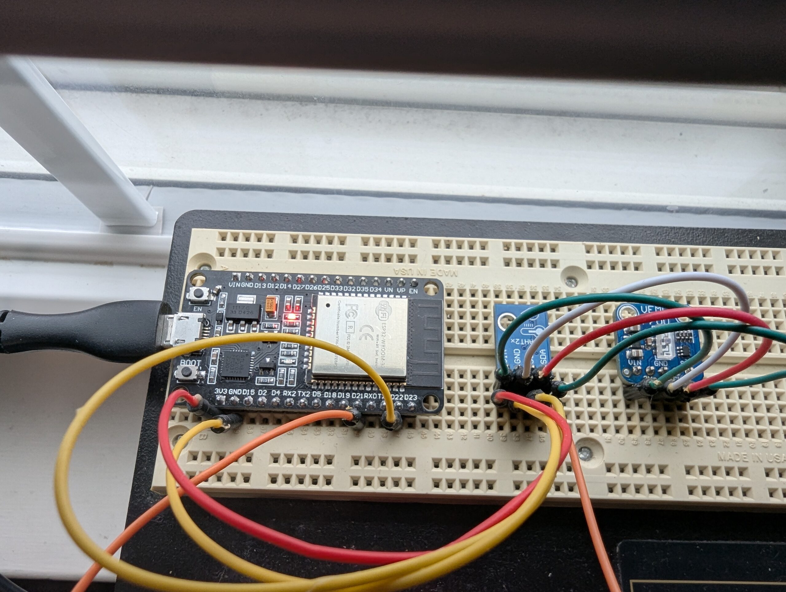
I chose to start by building the solar sensor. I laid out all the parts on a solderless breadboard and connected everything up using jumpers. Interfacing the ESP32 to the VEML7700 solar sensor was easy enough using I2C. I didn’t really need to, but I daisy chained in a temperature/humidity sensor for good measure. I had planned to use the Arduino IDE or the Espressif-IDF add-in for Visual Studio Code to program the ESP32. But then I learned about ESPHome, which already provided everything I wanted to do with the solar sensor. All I needed to do was create a simple YAML file containing some specifics about the ESP32 and the sensors attached to it. I decided to try it out. I knew I could always go back and write the code myself if ESPHome didn’t work out for me.
Here is a picture of the breadboard. This is after fixing some wires that my son’s cat helped to rearrange for me.
To setup the ESPHome development environment, I followed these instructions. Installing ESPHome Manually – ESPHome – Smart Home Made Simple. This installed Python and ESP home and provided the ESPHome command line application. Next, I created a configuration file, which I named ESPHomeConfig. Running the command “esphome dashboard ESPHomeConfig” started a web server and web-based application on my local computer. I accessed this application in my web browser at http://localhost:6052. This browser-based application permitted me to connect to my ESP32 through a USB connection and create the YAML file that specified what sensors were connected, how the ESP32 would communicate with them, and how to connect to my wireless network.
Creating this YAML file using examples from the Internet turned out to be very simple. I flashed the program to the ESP32 on the solar sensor and watched the logs as the ESP32 restarted and connected to my wireless network. It was able to read the temperature, humidity, and solar data from the attached sensors. I attempted to connect to the ESP32 via my web browser and was greeted with a page that displayed my data as well as a scrolling log of messages from the chip. Since the sensor was now online, I tried doing an OTA update. It worked with no issues.
Now that the solar sensor was operating properly, I needed a way to get the data to my weather station server. I saw that ESPHome provides a method for publishing data to an MQTT broker. This seemed like an easy way to transfer the data. The solar sensor would publish the data to MQTT, and my weather station server could subscribe to it. I added the appropriate configuration to the YAML file and just like that the solar sensor data was published to MQTT. It was fairly easy to add a MQTT data collector to the weather station server software. The software needed to do a few computations using the published solar data, but the equations are provided by the AS3935 chip manufacturer.
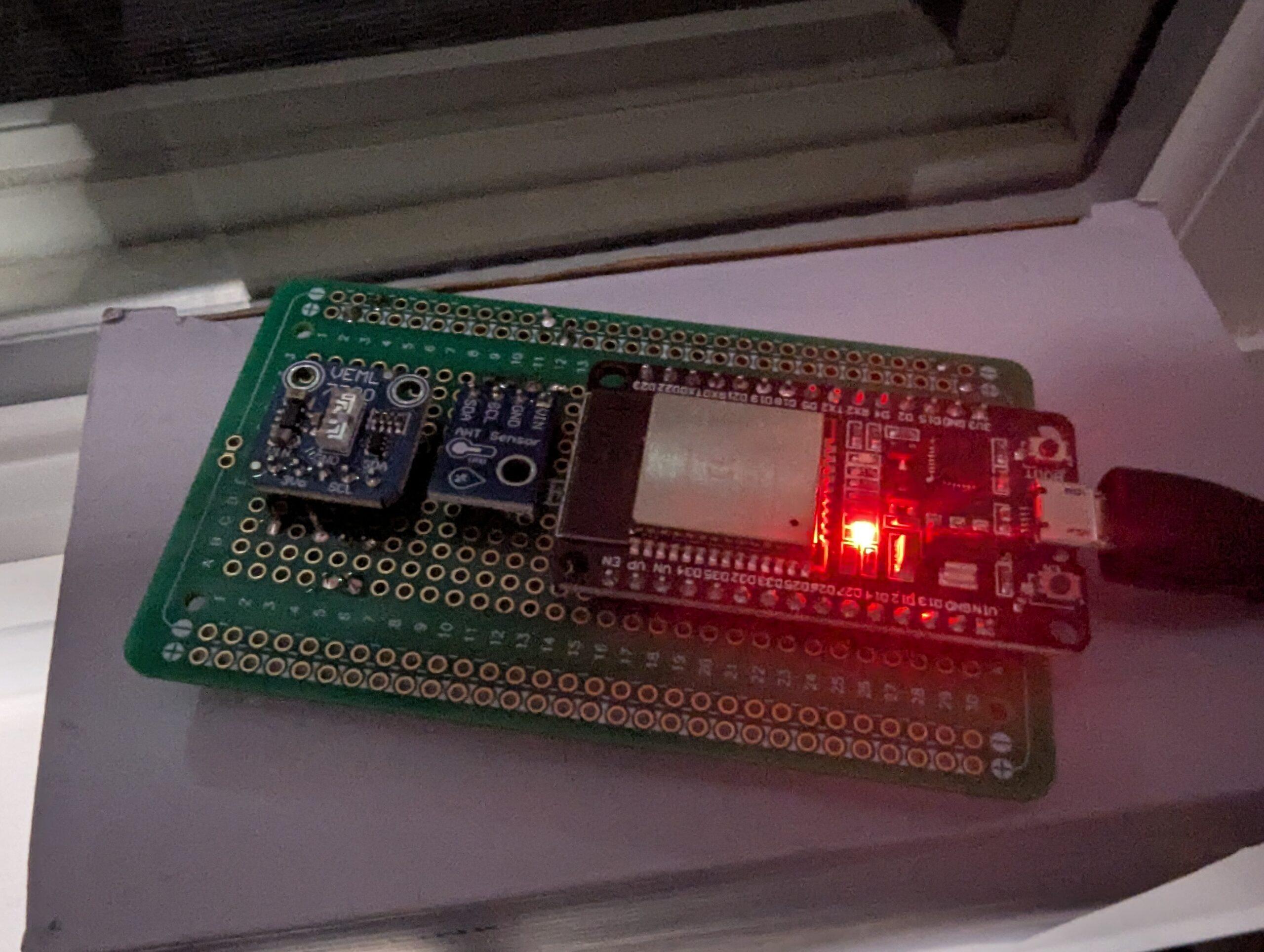
Now that the solar sensor was working, the data was being published to MQTT, and my weather server was able to retrieve the data and post it to my web site, I needed to work on packaging the sensor. The first thing was to wire everything more permanently, as the circuit was on a solderless breadboard with wire jumpers. I purchased some solderable breadboard PCB boards, laid out the chips, soldered them in place and wired everything back up. Upon testing I found that the permanent layout was working fine. Here is the solar sensor on the solderable breadboard.
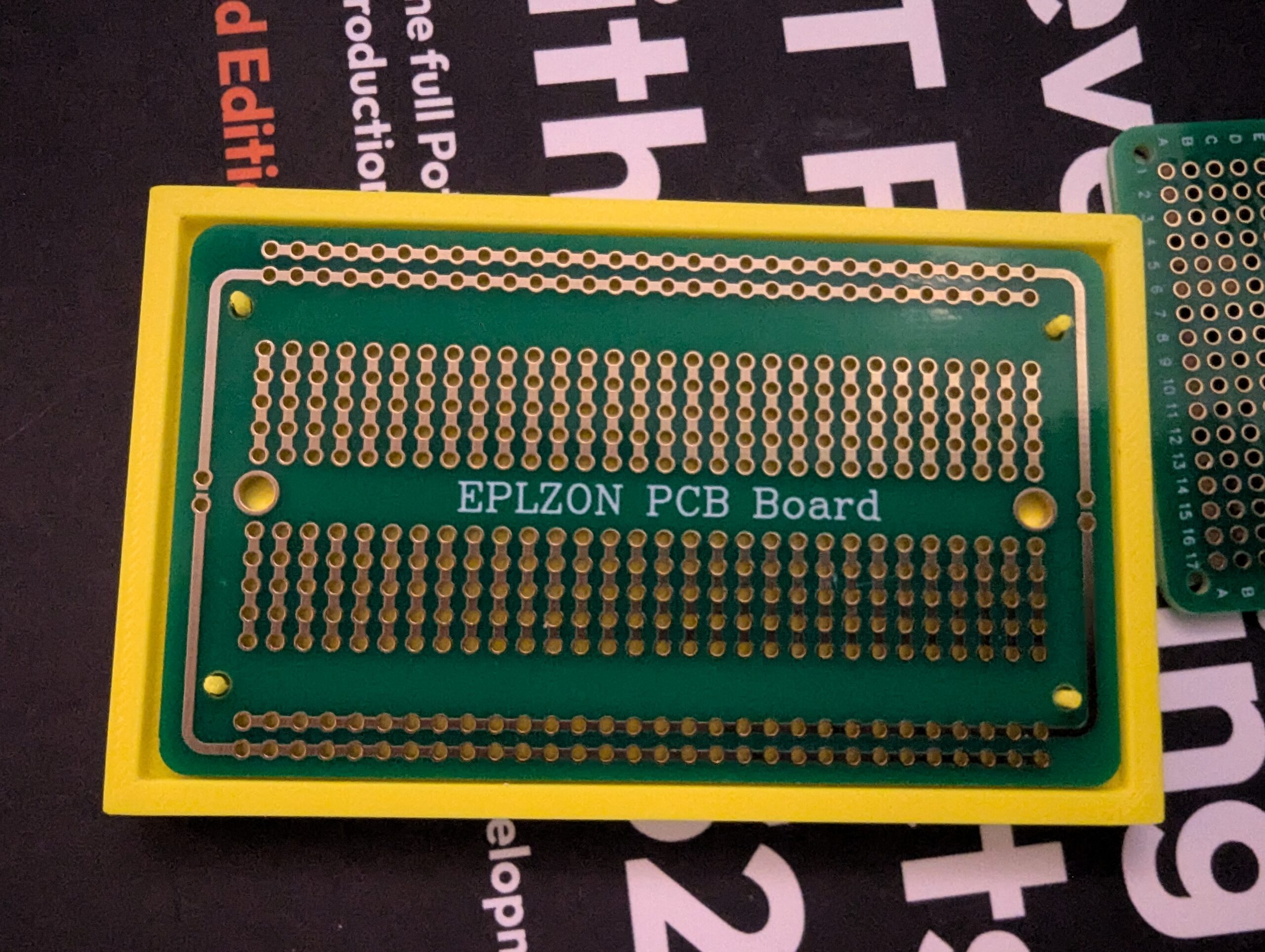
I started working on a 3D printed case for the circuit board, but that is still a work in progress. Here is how the solderable breadboard will fit in the case. This is just a prototype to make sure I got the dimensions correct and put the locating pins in the correct arrangement.
The only work left on this sensor is finishing the case for it and finding a suitable location to install it. I also need to build a lightning sensor to replace my old 1-wire version. That will be my next post.