Plug Computer and Web Site

I’ve been continuing to test with the Guruplug.  The software and computer have been very stable.  However, with my weather application running, the load average is at just above 1, with occasional spikes that go higher.  This is OK, but doesn’t leave room for everything else I had been running on my old weather server.

For my old weather server, I had written a Java application that would run periodically using cron, and aggregate information from the weather station, the National Weather Service, and a couple of other sources.  It would then build a Web site using a template and all of the aggregated information.  Finally, the application would upload the Web site to my ISP every few minutes.  Based on the load average, the Guruplug probably wouldn’t be able to handle that extra processing.  So I chose to offload the data downloads and Web page creation to the server at my ISP.

I created a shell script to download all of the data feeds I needed and ran it as a cron job.  I also created a cron job on the Guruplug to upload my weather data to my ISP once a minute.  No problem so far.  I had planned to run my Web site builder Java application on the server at my ISP.  That is, until I learned that my ISP doesn’t really support Java applications.  They don’t prohibit them.  Just discourage their use.  So I looked at using PHP to dynamically build my Web site, which the ISP does support.

That approach will work fine, but requires a significant amount of work on my part to recreate in PHP everything I was previously doing using Java.  The two languages have some similarities, but enough differences to make for a fair bit of work.  I started out with the basic weather data, as that was the simplest structure to work with.  That conversion was fairly straightforward.  I then started working on the statistics.  That has turned into a lot of work as I have several hundred data fields to parse from the XML statistics file.  I also should have formed the XML differently to make it easier to process.  Lesson learned for next time I create an XML schema.

After I finish with the statistics, I still need to do the weather forecast, advisories, traffic reports, and a couple of others.  I also want to change my pages to have a shared file for the header, navigation bar, and footer.  So a lot of work is left to be done before the Web site is ready for prime time.

Parts Scavenging

Today I did some browsing at the local hardware store for some parts. Here’s what I found and how I plan to use them.  I’ll also show a part I had in my “inventory” just waiting for the opportunity to be used.

I found some small flower pots made from UV resistant plastic that will work well for my radiation shield.  They are a different shape from the plastic bowls I had used previously, but are very similar in size.  I’ll have a detailed explanation (with photos) of how I used them in a future post.  For now, here’s a picture.  I plan to paint it a lighter color once I find some suitable paint for use on plastic.  The hardware store had some, but not in a light enough color. The white plastic paint was out of stock.

Plastic Flower Pot

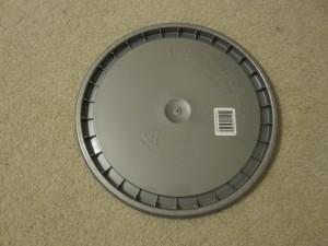
The next item I purchased was a plastic lid for a five gallon bucket.  It is very similar to what I currently use as a base for mounting my rain gauge.  Unfortunately it isn’t UV resistant, but at $1.28 US dollars, it was a steal.  I’m hoping it will last another 3 years, just like the first one I used.  I do plan to continue looking for a UV resistant flower pot base that will hold up better. But at least I know I have something I can use until I find something better. Here’s a picture.  I’ll provide more details and pictures when I finish making it into a rain gauge base.

Plastic Bucket Lid

Plastic Bucket Lid

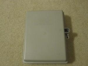
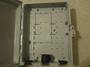
Finally, I had a UV resistant weatherproof plastic enclosure I purchased several months back.  These enclosures are typically used by cable and telephone companies, and hold up well.  I will use this to house the hub, anemometer board, and probably the barometer.  I need to mount the boards and drill some mounting holes.  I think it will work out really well. And yes, I did purchase this one. There isn’t some cable or phone company installation missing theirs.

Weatherproof Enclosure

Weatherproof Enclosure

Inside Weatherproof Enclosure

Inside Weatherproof Enclosure

I also connected the new lightning detector just to make sure it works correctly.  It is functionally identical to my old detector, so no software changes were required, other than adding the new address to my configuration file.  After making the changes and connecting the sensor, it worked without any problems.  I’ll put it in the housing I made for it when I’m ready to move everything outside.

New Anemometer

Today the new ADS anemometer arrived from Hobby Boards.  Here’s what was in the package
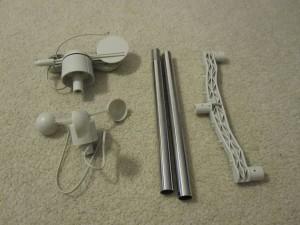
Anemometer Package Contents

I started out following the instructions to assemble it.  First put the pole together.
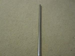
Assembled Pole

Assembled Pole

Next I installed the mounting arm.
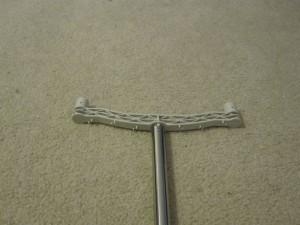
Mounting Arm Installed

Mounting Arm Installed

Then mount the anemometer and wind vane.
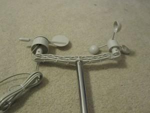
Sensors Mounted

Sensors Mounted

Then I added the controller board and connected the wires.  Or so I thought.  In my excitement I had stopped following the instructions.  I paid for that later on when I started testing.
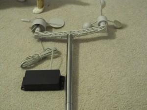
Completed Anemometer

Completed Anemometer

Next came time for some testing.  I hooked the anemometer board to my 1-Wire network and fired up the 1-Wire viewer application.  It showed the DS2423 and DS2438 chips from the anemometer board.  I updated the information in my application configuration file and started up the application.  Now the problems started.  The sensors would appear and disappear intermittently.  Sometimes the bus was shorted.  The anemometer board was intermittent.   Sensors would come and go.  This problem occured with both my application and the 1-Wire viewer.

I checked my power supply (this anemometer, my barometer, and the hub itself all require external power).  My voltmeter read right around 15 volts, which would meet the power requirements.  I removed all the other sensors and was able to isolate the problem as being with the anemometer board.  I finally decided to open the case for the anemometer, and I immediately saw my mistake.

If I had continued to follow the instructions I wouldn’t have had any problems, as they instructed me to open the case.  That’s where the jack is for connecting the sensors to the anemometer board.  I had connected the sensors directly to the 1-Wire bus.  This next picture clearly shows the third connector for the anemometer that isn’t visible until you open the case.  I want to stress that this was my mistake.  The instructions were clear on how to connect things (provided you read and follow them).
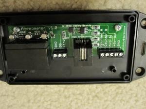
1-Wire Anemometer Board

1-Wire Anemometer Board

Now that I had everything wired up correctly, the board worked fine  My software updates to read the new sensors worked just as they should.  My only comment is that the wind direction sensor isn’t linear.  Directions such as NNE or ESE don’t cover as many degrees of rotation as the others.  In all fairness, the sensor only claims to have a resolution of 22.5 degrees.  And it probably does meet that specification.  For people who need greater accuracy than that Hobby Boards carries a higher quality sensor with a higher price tag to match.  This one will suit my needs.  Another plus is that this sensor doesn’t appear to have positions that are between directions and return an error like my old AAG anemometer would do.

Here’s some code for how to read the anemometer board and the ADS sensors.  A lot of this is specific to my application, but the basic logic should still make sense.  The formatting got messed up in moving the code to the Web.

Here’s code for the wind direction:

import com.dalsemi.onewire.OneWireException;
import com.dalsemi.onewire.adapter.DSPortAdapter;
import com.dalsemi.onewire.container.OneWireContainer26;

public class ADSWindDirectionSensor
{
    private static final int maxRetryCount = 3;
    private static final double WIND_DIR_ADJUST = 1.000;
    private OneWireContainer26 windDirectionDevice = null;

    public ADSWindDirectionSensor(DSPortAdapter adapter,
         SensorConfiguration config)
    {
        super(adapter, config);

        windDirectionDevice =
            new OneWireContainer26(adapter, config.getID());
    }

    public int getWindDirection()
    {
        int windDir = WIND_DIRECTION_ERROR;
        boolean bOK = false;
        int retryCount = 0;

        if (windDirectionDevice != null && isEnabled())
        {
            while(!bOK && retryCount < maxRetryCount)
            {
              try
              {
                if (this.isDebugFlag())
                {
                  ErrorLog.logError("Wind Dir: Device = " +
                    windDirectionDevice.getName() + "  ID = " +
                    windDirectionDevice.getAddressAsString());
                }

                this.getPath().open();

                // read 1-wire device's state
                byte[] state = windDirectionDevice.readDevice();

                // Read sensor's output voltage
                windDirectionDevice.doADConvert(
                    OneWireContainer26.CHANNEL_VAD, state);
                double Vad = windDirectionDevice.getADVoltage(
                    OneWireContainer26.CHANNEL_VAD, state);

                // Read the sensor's power supply voltage -
                //    mostly for debugging
                windDirectionDevice.doADConvert(
                           OneWireContainer26.CHANNEL_VDD, state);
                double Vdd = windDirectionDevice.getADVoltage(
                           OneWireContainer26.CHANNEL_VDD, state);

                // compensate for supply variations
                Vad = Vad * WIND_DIR_ADJUST;

                // convert the A to D voltage to a wind direction
                windDir = lookupWindDir(Vad);

                if (this.isDebugFlag())
                {
                  ErrorLog.logError("Wind Dir A to D = " + Vad +
                    " Wind Dir Supply = " + Vdd +
                    " Wind Direction  = " + windDir);
                }

                if (windDir == WIND_DIRECTION_ERROR)
                {
                  if (isDebugFlag())
                  {
                    ErrorLog.logError("Wind dir: ERROR - Vad: " +
                       Vad + " Vdd; " + Vdd);
                  }

                  retryCount++;
                }
                else
                {
                  bOK = true;  
                  if (isDebugFlag())
                  {
                    ErrorLog.logError("Wind dir: - Vad: " +
                      Vad + " Vdd; " + Vdd);
                  }
                }

            this.getPath().close();
        }
        catch (OneWireException e)
        {
            if (this.isDebugFlag())
            {
            ErrorLog.logError("Error Reading Wind Direction: " + e);
            }
            retryCount++;
        }
        }
        if (retryCount >= maxRetryCount)
        {
        ErrorLog.logError("Wind Direction: Retry count exceeded");
        }
    }

    return windDir;
    }

    // convert wind direction A to D results to direction value
    private int lookupWindDir(double volts) // ADS
    {
      int direction = WIND_DIRECTION_ERROR;

      for (int i = 0; i < 16; i++)
      {
      if((volts <= lookupTable[i] + 0.04) &&
                   (volts >= lookupTable[i] - 0.04))
      {
          direction = i;
          break;
      }
      }

      return direction;

    }

    static final double lookupTable[] =
    {
    2.69, // N
    6.52, // NNE 1
    5.99, // NE  2
    9.38, // ENE 3
    9.30, // E   4
    9.53, // ESE 5
    8.51, // SE  6
    9.01, // SSE 7
    7.60, // S   8
    7.98, // SSW 9
    4.31, // SW  10
    4.62, // WSW 11
    0.92, // W   12
    2.23, // WNW 13
    1.57, // NW  14
    3.57, // NNW 15
    };

}

Here’s the wind speed code:

import com.dalsemi.onewire.OneWireException;
import com.dalsemi.onewire.adapter.DSPortAdapter;
import com.dalsemi.onewire.container.OneWireContainer1D;

public class ADSWindSpeedSensor
{
    private OneWireContainer1D windSpeedDevice = null;
    private static final int maxRetryCount = 3;
    private long lastCount = 0;
    private long lastTicks = 0;

    /**
     *
     * Constructor that will instantiate the wind speed sensor
     * of the specified
     * ID on the specified adapter.
     *
     * @param adapter
     *            The 1-Wire adapter this sensor is connected to.
     * @param config
     *            The SensorConfiguration that specifies all the
     *            parameters for this sensor.
     *
     */
    public ADSWindSpeedSensor(DSPortAdapter adapter,
            SensorConfiguration config)
    {
    super(adapter, config);

    windSpeedDevice = new OneWireContainer1D(adapter, config.getID());
    }

    /**
     * Method to read the wind speed sensor and return the speed in 
     * miles per hour.
     *
     * @return The wind speed in miles per hour. If there was not a 
     *         valid reading, return Float.MIN_VALUE.
     *
     */
    public float getWindSpeed()
    {
    float windSpeed = Float.MIN_VALUE;
    boolean bOK = false;
    int retryCount = 0;

    if (windSpeedDevice != null && isEnabled())
    {
        while (!bOK && retryCount < maxRetryCount)
        {
        try
        {
            this.getPath().open();

            if (this.isDebugFlag())
            {
            ErrorLog.logError("ADS Wind Speed: Device = " +
                      windSpeedDevice.getName() +
                      " ID = " + windSpeedDevice.getAddressAsString());
            }

            // read wind counter & system time
            long currentCount = windSpeedDevice.readCounter(15);
            long currentTicks = System.currentTimeMillis();

            if (lastTicks != 0)
            {
            // calculate the wind speed in MPH based on
            //  the revolutions per second
            windSpeed = (float) ((1.25 *(currentCount-lastCount)) /
                 ((currentTicks-lastTicks) / 1000f));
            }

            if (this.isDebugFlag())
            {
            ErrorLog.logError("Count = " + (currentCount-lastCount)
                    + " during " +
                (currentTicks-lastTicks) + "ms calcs to " + windSpeed);
            }

            // remember count & time
            lastCount = currentCount;
            lastTicks = currentTicks;
            bOK = true;

            this.getPath().close();
        }
        catch (OneWireException e)
        {
            if (this.isDebugFlag())
            {
            ErrorLog.logError("Error Reading Wind Speed: " + e);
            }
            retryCount++;
        }

        }

        if (retryCount >= maxRetryCount)
        {
        ErrorLog.logError("Wind Speed: Retry count exceeded");
        }
    }

    return windSpeed;
    }

}

Time for some more testing, and create a way to attach this anemometer to the rest of the weather station.  I also received a new photocell and a new lightning sensor to play with.  I need to replace my humidity sensor chip and build the new radiation shield.  Lot’s more fun to come.

Computer Switchover

I ran a 2 day test running the application continuously, to make sure the software was stable on my workstation with the DS9490.  I had been having some problems with the DS9097 connected through an inexpensive USB to serial converter.  After running for a while, the software would lose communication with the DS9097 adapter.  I attributed the problems to the converter, as the software has been running successfully for years, while the converter is brand new.  I had heard rumors that converters using the FTDI chip are more stable than the ones using the Prolific chip, but I have no hard evidence to substantiate that claim.  This converter uses the Prolific chip, but was what I had available and was inexpensive.  I really didn’t think I would see any significant problems with it.  Switching to the DS9490 cleared up the periodic loss of communication with the adapter.

So now I’m switching to the Guruplug to host my application, initially using the DS9097 and USB to serial converter.  I’m hoping the Linux drivers are better then the Windows ones.  I’ll look at switching to the DS9490 adapter later.  I installed all the libraries I needed, including getting RXTX setup.  The permissions on /dev/ttyUSB0 caused me to do some debugging, as I kept getting a message saying that RXTX wasn’t configured correctly.  Turned out to be a simple permissions problem. When udev detects the USB to serial converter, it creates the /dev/ttyUSB0 device with root permissions. Set the permissions using chmod and all is well for now. I still need to create a udev rule to set the permissions when it detects the USB to serial converter and creates the corresponding device.  But permissions are set for now.

I installed the application and am running it in test mode.  So far so good.  It’s kind of sluggish compared to my workstation, but it does find all the sensors and can read them.  I’ll leave it running for a few days and see how stable it is.

I also got an email from Hobby Boards confirming the shipment of my new anemometer and the assorted repair parts.  Should have plenty to do this weekend after all my new goodies arrive. Still need some replacement UV resistant plastic parts. Got some flower pots for the radiation shield that are made from UV resistant plastic. Will be posting about that project soon. I also need to return to the garden center and look for a few more plastic goodies, as well as any new PVC fittings I may need to mount the anemometer.

Update: After running for two days with no issues or lockups I think I can declare the new combination stable.  The load bounced around more than I would like, with the 1 minute average going up and down from .4 to as high as 1.5. But the 5 minute average managed to stay below 1.  Might be related to garbage collection, but I haven’t investigated at all yet so I’m just guessing at this point.  I may want to do some JVM tuning down the road, but it should be OK for now.

Library Mixup

I have two 1-Wire adapters that permit a computer to act as a bus master on a 1-Wire network.  The DS9097 is a serial to 1-Wire adapter, and requires a computer with a serial port.  The DS9490 is a USB to 1-Wire adapter and requires a USB port. I have used the DS9490 with my Windows workstation, and the DS9097 with my Linux weather station computer.  I needed a different plan with the Guruplug, as it doesn’t have a serial port like the old computer did.  I have an inexpensive USB to serial converter that could be used with the DS9097 if needed.

I had downloaded and installed the 1-Wire API for Java, but haven’t been able to get it to work properly with the DS9490 USB adapter on my current Windows workstation. It worked fine with my DS9097 serial port adapter.  I had it working previously (several years ago), but have since upgraded the OS on my workstation from Windows XP 32 bit to Vista 64 bit and then to Windows 7 64 bit.  Yes, it’s been a while since I tested my weather application on this workstation.  I hadn’t needed to run the application on my workstation since the XP days.  I just made changes as needed on Windows and tested on Linux, where I was running the DS9097 serial port adapter.  When I first ran into problems on my Windows workstation, I switched to the serial port adapter until I could diagnose the problem, chalking it up to a 32bit/64 bit driver issue.

Well, I finally got back to looking at the issue.  I ran the 1-Wire viewer that came with the Java API on my workstation, and it couldn’t see the USB adapter.  When I downloaded and ran the jump start version direct from the Dallas web site, it did see the adapter.  Also, the 64 bit version bundled with the driver could see the adapter as well.  I downloaded the newer source for the one bundled with the drivers, so I could study and compile the code.  It referenced classes and methods that weren’t in my 1-Wire API jar file.  I had  the library source as part of the API, and those classes weren’t there at all.  Also, the source for the 1-Wire viewer used the same methods for discovering and opening the adapter that my application was using.  So I couldn’t compile the viewer locally, and the source used the same methods for opening the adapter that I was using.

After some searching, I found that Dallas has an FTP site, where they had a newer version of the library and source than what was included in the official API.  Once I installed this “secret” library in place of the official one, the USB adapter worked fine.  For anybody stuck with the same problem as I was, here is a link to the FTP site.  Grab the onewireapi.jar file (and the corresponding source file if desired), and replace the one that came with the official API. The one wire viewer application source may provide some useful examples as well.

Hardware Inventory

So now it’s time to check out all the sensors and see what work is required there.  Here’s where things stand

Sensors

  • Barometer – works fine.  Compared the readings with a local weather station and the calibration is still good too.
  • Temperature – work fine
  • Humidity – shows up on net, but humidity value is always 100%.  After several weeks indoors it appears to be reading accurately now.  However I have a replacement Honeywell HIH-4021 humidity sensor chip ready to install on the board.  Should be an easy fix
  • Solar – shows up on net.  Not sure about the photocell.  Ordered a replacement photocell to install.  This part has a lower peak voltage than the previous photocell, so some calibration may be necessary.  The old photocell tended to cause clipping under bright sunlight, so this should be an improvement.
  • Lightning – completely dead.  Ordered a new board from Hobby Boards.
  • Anemometer – Wind speed appears to work.  Direction is intermittent (mostly not working).  Opened up the anemometer and cleaned out all the dirt and bug remains.  Helped some, but I think the best course of action is to replace it.  Ordered an ADS anemometer from Hobby Boards.  Changing anemometer brands required some software changes as well.  Nothing too difficult.  The wind speed sensor is similar to the old AAG one, but with a different formula for calculating the wind speed.  Wind direction is based on one voltage returned rather than four like the old AAG sensor.
  • Rain – seems to work fine after a good cleaning.  However I need to rewire it using an RJ45 rather than RJ11 connector.  I believe it originally came with an RJ45 and I changed it.  But I can’t remember for sure.

Hardware

  • Temp/Humidity/Solar sensor housing (homemade radiation shield) – U/V has taken it’s toll.  The plastic bowls I had used are brittle and cracking.  Need to replace them with something more U/V resistant.  The fan (a computer case fan) still works.
  • Base for rain gauge – this was homemade from a plastic lid from a laundry detergent container.  U/V has made it brittle as well.  Maybe the base for an outdoor flower pot will work as a replacement.
  • Stand and supports – PVC tubing is holding up fine.  Just want to make sure everything is secure.  May even paint it this time around to make it look a little less homemade.

Nothing that can’t be fixed.  I have parts on order, and am scouring the hardware stores for U/V resistant plastic parts.  Future posts will outline all of the fixes as I make them.

Software Update

My next step was to modify my software so that it would work with the hub.  In order to read a sensor, the software would need to know the switches to enable and disable for each sensor, and would need to enable those switches prior to reading the sensor.

My first thought was to include that information in the configuration file.  However this approach would be inflexible, and would not permit multiple hubs as I was only planned to include the information for one switch.

My next idea was to search the network, locate the switch, and map out the path to each sensor.  I got that working, but it still limited me to one switch as I was not searching each path for any additional switches.

Further research revealed that there is a NetworkMonitor class included in the 1-Wire API that periodically traverses the 1-Wire net and sends a message whenever a a sensor appears or disappears on the network.  It uses the Observer design pattern, where the application wanting to receive notifications provides a class instance with the callback methods to the monitor.  The information in the callback includes the full path to the sensor through multiple switches if any.  This sounded like exactly what I wanted.  Support for multiple switches and the ability to dynamically update whenever a sensor was added, removed, or even moved from one port to another.

Got it working fine in a stand alone program that just monitored the network.  When I integrated the network monitor into my program the behavior was different.  Every time it traversed the network it showed all the sensors as new.  Then it would throw an exception after a few minutes and stop.  Some kind of interaction between my code to read the bus and the network monitor.  So I moved on to the approach I used as my final solution (for now).  This was still my favorite approach, as it permits the network to be dynamic, adapting to sensors coming and going on the bus.  I intend to revisit the idea sometime down the road.

For my next attempt, at program start up I manually traversed the entire network, including any nested switches using a breadth first search algorithm.  I created an OWPath object (a class provided in the 1-Wire API) for each sensor found on the net so that the path could be opened and closed when reading the sensor.  It doesn’t dynamically adapt to sensors moving or coming and going while the application is running, but it works well for building a static map of the network.  I will have to restart the application if the sensors change or move in order to build a new map.  I also can log any sensors found on the bus but not in my configuration file, or sensors in the configuration file not found on the bus.  I may come back to the NetworkMonitor approach again, but I’m satisfied for now.

For anybody interested, here’s my code for traversing the 1-Wire network.  There are a few things that are specific to my application, but the logic is hopefully clear enough to adapt.  Sorry, but the formatting got a bit munged.

   
    private Hashtable<String, OWPath> walkNet(DSPortAdapter adapter)
    {
        // vector for holding a list of paths to be searched
        Vector<OWPath> pathsToSearch = new Vector<OWPath>();
        boolean searchResult = false;

        // hash table for holding the OWPath objects for each
        //   device container.
        Hashtable<String, OWPath> devicePathHash =
            new Hashtable<String, OWPath>();

        try
        {
            // seed list with main branch
            pathsToSearch.addElement(new OWPath(adapter));

            // acquire the adapter
            adapter.beginExclusive(true);

            // setup the search
            adapter.setSearchAllDevices();
            adapter.targetAllFamilies();
            adapter.setSpeed(DSPortAdapter.SPEED_REGULAR);

            // walk path and get all devices on branch.
            // if any switches are found, add them to the list
            //   of paths to search
            // search through all of the paths
            for (int i = 0; i < pathsToSearch.size(); i++)
            {
                // set searches to not use reset
                adapter.setNoResetSearch();

                // get the next path to search and open it
                OWPath path = (OWPath)pathsToSearch.elementAt(i);

                try
                {
                    // try to open the current path
                    path.open();
                }
                catch(Exception e)
                {
                    // if opening the path failed, log an error and
                    //    continue on to the next path
                    ErrorLog.logError("walkNet(): Error opening path "
                        + path.toString());
                    continue;
                }

                // get the devices on the currently open path
                searchResult = adapter.findFirstDevice();

                // loop while devices found
                while (searchResult)
                {
                    // get the 1-Wire address
                    String address = adapter.getAddressAsString();

                    // check if the device already exists in the hash
                    //    table of addresses
                    if (!devicePathHash.containsKey(address))
                    {
                        OneWireContainer owc =
                          adapter.getDeviceContainer(address);

                        // check to see if it's a switch.  If so, add
                        //    it to the paths to be searched
                        //    if we haven't already searched it
                        if (owc instanceof SwitchContainer)
                        {
                            SwitchContainer sc = (SwitchContainer)owc;
                            byte[] state = sc.readDevice();
                            for (int j = 0;
                                   j < sc.getNumberChannels(state); j++)
                            {
                                OWPath tmp = new OWPath(adapter, path);
                                tmp.add(owc, j);
                                if (!pathsToSearch.contains(tmp))
                                {
                                    pathsToSearch.addElement(tmp);
                                 }
                            }
                        }

                        // save off the address and path
                        synchronized(devicePathHash)
                        {
                            devicePathHash.put(address, path);
                        }
                    }
                    // check if the existing device moved
                    else if (!path.equals((OWPath)
                                devicePathHash.get(address)))
                    {
                        // if it has moved, add the new
                        //    address/path pair
                        synchronized(devicePathHash)
                        {
                            devicePathHash.put(address, path);
                        }
                    }

                    // find the next device on this branch
                    path.open();
                    searchResult = adapter.findNextDevice();
                }

                path.close();
            }

            // clean up after ourselves
            adapter.setSearchAllDevices();
            adapter.endExclusive();
        }
        catch (OneWireException e)
        {
            ErrorLog.logError("Error Serching the 1-Wire Bus");
        }

        return devicePathHash;

    }

Hub and Spoke

A simple 1-Wire network connects all the sensors on a bus in a daisy chain configuration. This allows one device to potentially take down the entire bus. It actually worked pretty reliably for me for several years. But it doesn’t lend itself very well to taking one sensor our of the chain for service while keeping the rest of the chain operational.

Another consideration is power for some of the sensors. In a 1-Wire network, the devices draw power from the 1-Wire bus, known as parasitic power. This makes it easy to get power to the sensors. Since this is the same bus used for data and signalling, available power is limited and drawing power from this bus may affect the sensors being read.

Another addition I wanted to make is to add external power for the sensors, again in the name of reliability. I experimented with sending power over some unused wires on my cables before, but never implemented it as the bus architecture without power worked for me initially.

I was able to find a solution to address both of these issues. Another kit from Hobby Boards.

Hobby Boards 1-Wire Hub

This one is their 6 channel hub. It provides 6 channels for connecting 1-Wire devices, and provides regulated external power on the unused wires on the cables. This will allow me to group sensors on separate channels, and to provide external power to them as well.  I built the kit in an evening. Be warned, the Hobby Boards kits use surface mount parts. Easy to lose parts and can be tricky to solder. But I got it built and tested. All channels working and power is available. Next installment is the software updates I made to support the hub.

New Station Computer

While very reliable, my weather station computer was old, outdated, and power hungry.  While searching for an appropriate upgrade, I came across plug computers  They are small (slightly larger than a pack of cigarettes), power efficient (draws less than 5 watts), less expensive than a full size computer, and runs embedded Linux.  I ordered a Guruplug Server from Global Scale Technologies, along with their JTAG accessory in case I managed to brick the computer.  Good thing too, as it took me no time at all (like maybe 2 hours) to render it un-bootable.  How did I manage to do that, you might ask.  I did the following:

  • apt-get update
  • apt-get upgrade
  • apt-get dist-upgrade

After that the computer failed to boot.  That started me down the path of getting the JTAG to work and upgrading uBoot.  Then downloading and installing the kernel and file system.  Now it could boot again.  I ended up adding an 8GB Class 10 microSD card and installing Debian Linux on it.  Then modifying the uBoot parameters to permit booting from the microSD card. There were additional tasks, such as getting it to be a stable wireless client, installing software, and configuring it the way I wanted it to.

Existing Station Hardware

First I should talk about what hardware I already have in place. The weather station consists of several 1-Wire sensors. It has an AAG anemometer for measuring wind speed and direction. The temperature, humidity, solar, barometric pressure, and lightning sensors are all kits sold by Hobby Boards. The rain sensor is made by Rainwise and modified for 1-Wire by Hobby Boards. I built the kits along with the housing and mounting. The base structure is made from PVC tubing. It has a fan aspirated radiation shield I made from threaded rod, plastic bowls, and a computer case fan. The rain gauge is mounted on the plastic lid from a tub of laundry detergent. Several adapters, t-fittings, and a shower drain tie it all together. The problem is that over time, UV radiation caused the plastic bowls and and lid to deteriorate. That, along with the fact that some of the sensors had become intermittent, are the reasons I took down the weather station for a redesign. More on the fix, hopefully with detailed pictures to come. Also coming soon will be a write up of my new weather station computer.  The current computer is an ancient Pentium 3 450 running Fedora Core 6.